Friday, April 30, 2010

Revit Architecture User Interface

Navigating the User Interface
One of the advantages of Revit Architecture is its ease of use, specifically its clear user interface. The Revit Architecture window is arranged to make navigation easy. Even the toolbar buttons are labeled, making it easy to understand what each button represents. Revit Architecture uses standard Microsoft Windows conventions. If you have used any other product that follows these conventions, learning Revit Architecture is much easier.In the following illustration, the user interface is labeled. In the steps that follow, you navigate and become familiar with the user interface.
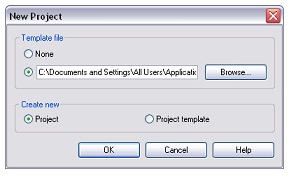
Start a new project
On the Standard toolbar, click (New). This creates a new project based on the default template.


The Title Bar
Place the cursor at the top of the user interface.
The title bar contains the name of the project and the view that is currently open.


By default, new projects are numbered consecutively until saved with a new name. In addition,
the Level 1 floor plan view is the default open view.

TIP
The view opened and the view names are dependent on the template on which the project is based.

The Menu Bar
The menu bar across the top of the window includes standard menu names such as File, Edit,
and View. Click View menu ? Zoom.


Many of the commands have shortcut keys, which are listed on the menu. For example, the
shortcut key for Zoom in Region is ZR. While working in the drawing area, you type the required
key combination to perform the command. Another time-saving tool for selecting commands is to place the cursor in the drawing area and right-click. A shortcut menu displays a list of available commands, depending on the function you are performing and what is currently selected.


The Toolbar
Click Window menu ? Toolbar.
There are several toolbars across the top of the window beneath the menu bar. The toolbar
buttons represent common commands. You can control the visibility of the toolbars and turn
the text labels on or off using the Window ? Toolbar menu. You can use the toolbar grips to
resize and move each toolbar.


The Options Bar

  • Click Modelling menu ? Wall.
The bar beneath the toolbars contains wall design options. The Options Bar is context-sensitive
and varies depending on the tool or selected component.

  • Click Modelling menu ? Door.
The design options available on the Options Bar are now applicable to doors. On the left side
of the Options Bar, a door type is specified.

The Type Selector
The drop-down list on the left side of the Options Bar is called the Type Selector. Select the
drop-down list to view the list of doors.
The Type Selector is a context-sensitive drop-down list. When you select the Door tool, the Type
Selector displays a list of doors available in the project. The list of elements in the Type Selector
is identical to the elements listed in the Families branch of the Project Browser under the
respective category.

  • Click Modelling menu ? Wall.
  • In the Type Selector, select the drop-down list to see the walls that are available.
You can use the Type Selector in 2 ways:
  • You can select an element type before you add the element to the building model. For example, when you add a door, the door type that displays in the Type Selector is the door type that will be added to the building model.
  • You can use the Type Selector to change an element type after it has been added to the
    building model. In the drawing area, you can select any element and then change its type
    using the Type Selector.

The Design Bar
  • Click Window menu then Design Bars.
The Show Design Bars dialog displays.


The Design Bar is located on the left side of the interface, immediately below the Type Selector.
There are 10 tabs in the Design Bar, containing buttons grouped by function. You can control
which tabs display by selecting them in the Show Design Bars dialog.
Click OK.
Each tab contains frequently used commands that are also available from the menu bar.
Basics tab: commands for creating most basic building model components
  • View tab: commands for creating different views in the project
  • Modelling tab: commands to create model elements
  • Drafting tab: commands for adding annotation symbols and creating sheet details forconstruction documents
  • Rendering tab: commands for creating rendered images
  • Site tab: commands for adding site components and producing site plans
  • Massing tab: commands for creating conceptual designs with masses
  • Room and Area tab: commands for making room and area schemes and plans
  • Structural tab: commands for adding structural components to the project
  • Construction tab: commands for creating construction industry information
To access the commands in a tab, click the tab in the Design Bar. The respective commands
display on the Design Bar.

TIP: You can control the visibility of each tab by right-clicking on the Design Bar and selecting the tab from the shortcut menu.
The Project Browser
To the right of the Design Bar is the Project Browser. In the Project Browser, select Views (all).
You can use the Project Browser to quickly manage the views, schedules, sheets, reports, familie
and groups of your current project:
  • Right-click in the browser to add, delete, and rename views, families, and groups.
  • The browser is organized by view type (floor plans, elevations, 3D), family category (doorwalls, windows), and group name. Expand or collapse the browser list by clicking the + or next to the name.
  • To open a view, double-click its name.
  • You can also drag and drop from the browser into the drawing area, making it easy to add a family or group to the project or add a view to a sheet.
  • The browser is dockable, so you can reposition it by dragging the Project Browser title bar to a new location.
In the Type Selector, scroll through the sorting options available for the Project Browser.
  • Click Settings menu ? Browser Organization.
You can create and modify Project Browser organization schemes for views and sheets. After
creating a browser organization scheme, you can instantly change the sorting within the Project
Browser by selecting the scheme in the Type Selector.
  • In the Browser Organization dialog, click Cancel.

The Status Bar
  • On the Basics tab of the Design Bar, click Wall.
  • Place the cursor near the center of the drawing area. Do not click.
The cursor displays as a pencil.


In the bottom left corner of the window, the status bar provides information regarding what
you should do next. In this case, it tells you to "Click to enter wall start point."
  • On the Design Bar, click Modify to end the Wall command.
You can control the status bar visibility from the Window menu. The status bar also provides
information, in conjunction with tooltips, regarding selected elements in a view. When you
place the cursor over an element, it highlights and the status bar displays the element name.
  • Place the cursor over the elevation symbol arrow on the left side of the drawing area.
The elevation symbol consists of two parts: the main symbol and the elevation directional arrow
(a triangle). Make sure you place the cursor over the elevation directional arrow. It highlights
when the cursor is over it.
In the status bar, notice that the name of the highlighted element is Views : Elevation : West.
  • Press TAB, and notice that the highlighted element switches to the main elevation symbol, Elevations : Elevation : Elevation 3.
When attempting to select a specific element in a complex or crowded view, you can use the
status bar and TAB to switch between elements and select the desired element.

Read more...

Introduction To Revit Architecture


This introduction helps you get started with the Revit Architecture 2009 tutorials and presents the fundamental conceptsof the product, including:

  • how Revit Architecture works.
  • the terms used when working with the product.
  • how to navigate the user interface.
  • how to perform some common tasks in the product.


Using the Tutorials

In this lesson, you learn how to use the Revit Architecture tutorials, including where to find the training files and how to create a new Revit Architecture project from a template file.
The Contents tab of the Revit Architecture Tutorials window displays the available tutorial titles. Expand a title for a list of lessons in the tutorial. Expand a lesson title for a list of exercises in the lesson.

NOTE You may find it helpful to print a tutorial to make it easier to reference the instructions as you work in Revit Architecture. The tutorials are also available in PDF format by clicking Help menu ? Documents on the Web in Revit Architecture.

Accessing Training Files
Training files are Revit Architecture projects, templates, and families that were created specifically for use with the tutorials. In this exercise, you learn where the training files are located, as well as how to open and save them.

Where are the training files located?
Training files, by default, are located in C:\Documents and Settings\All Users\Application
Data\Autodesk\RAC 2009\Training. Training files are grouped into 3 folders within the training folder:
  • Common: generic files often used to teach a concept. These files are not dependent on imperial or metric units. Common file names have a c_ prefix.
  • Imperial: files for users working with imperial units. Imperial file names have an i_ prefix.
  • Metric: files for users working with metric units. Metric file names have an m_ prefix.
NOTE Depending on your installation, your training folder may be in a different location. Contact your CAD manager for more information.

IMPORTANT Content used in the tutorials, such as templates and families, is located and accessed in the training files location. Although this content may be installed in other locations on your system, all content used in the tutorials is included in the training files location to ensure that all audiences access the correct files.

What is a training file?
A training file is a Revit Architecture project that defines a building information model and views of the model that are used to complete the steps in a tutorial. Many tutorials include a Training File section that references the training file to be used with the tutorial. In other tutorials, you create a project from a template, rather than opening an existing training file.

Open a training file
1 Click File menu ? Open.
2 In the left pane of the Open dialog, scroll down, and click the Training Files icon.
3 In the right pane, double-click Common, Imperial, or Metric, depending on the type of training
file.

Save a training file
5 To save a training file with a new name, click File menu ? Save As.
In many cases, the work you do in a project during a tutorial exercise becomes the starting point
for the next exercise. In many tutorials, you create a project or modify an existing project, save
the changes, and use the saved version of the file to begin the next exercise or lesson.

6 Complete the information in the Save As dialog:
  • For Save in, select the folder in which to save the new file.You can save the file in the appropriate Training Files folder or in another location.
Note where you save the file so you can open it for additional exercises as required.
  • File name, enter the new file name. A good practice is to save the training file with a unique name after you have made changes. For example, if you open c_settings.rvt and make changes, you should save this file with a new name such as c_settings_modified.rvt.
  • For Files of type, verify that Project Files (*.rvt) is selected, and then click Save.
Create a project from a template
7 To create a project from a template, rather than using an existing training file, click File menu? New ? Project.


8 In the New Project dialog, under Create new, select Project.
9 Under Template file, verify the second option is selected, and click Browse.
10 In the left pane of the Choose Template dialog, click Training Files, and open Imperial\Templates.

11 In the Choose Template dialog, review the Revit Architecture templates.
Templates are available for specific building types: commercial, construction, and residential.
Each template contains predefined settings and views appropriate for the corresponding building
type. For most tutorial projects, you will use the default template, and customize the project as
necessary.
12 Select default.rte, and click Open.
13 Click OK.

please share if you find this helpful

Read more...

Thursday, April 29, 2010

Getting Started with Matlab


Download Video tutorial about Getting Started with Matlab


You can start MATLAB by double clicking on the MATLAB icon that should be on the desktop
of your computer. This brings up the window called the Command Window. This window
allows a user to enter simple commands. To clear the Command Window type clc and next press
the Enter or Return key. To perform a simple computations type a command and next press the
Enter or Return key. For instance,
s = 1 + 2
s =
3
fun = sin(pi/4)
fun =
0.7071
In the second example the trigonometric function sine and the constant are used. In MATLAB
they are named sin and pi, respectively.
Note that the results of these computations are saved in variables whose names are chosen by the
user. If they will be needed during your current MATLAB session, then you can obtain their
values typing their names and pressing the Enter or Return key. For instance,
s
s =
3
Variable name begins with a letter, followed by letters, numbers or underscores. MATLAB
recognizes only the first 31 characters of a variable name.
To change a format of numbers displayed in the Command Window you can use one of the
several formats that are available in MATLAB. The default format is called short (four digits
after the decimal point.) In order to display more digits click on File, select Preferences…, and
next select a format you wish to use. They are listed below the Numeric Format. Next click on
Apply and OK and close the current window. You can also select a new format from within the
Command Window. For instance, the following command
format long
changes a current format to the format long. To display more digits of the variable fun type
fun
fun =
0.70710678118655
To change a current format to the default one type
format short
fun
fun =
0.7071
To close MATLAB type exit in the Command Window and next press Enter or Return key. A
second way to close your current MATLAB session is to select File in the MATLAB's toolbar
and next click on Exit MATLAB option. All unsaved information residing in the MATLAB
Workspace will be lost.

There are three kinds of numbers used in MATLAB:
• integers
• real numbers
• complex numbers
Integers are enterd without the decimal point
xi = 10
xi =
10
However, the following number
xr = 10.01
xr =
10.0100
is saved as the real number. It is not our intention to discuss here machine representation of
numbers. This topic is usually included in the numerical analysis courses.
Variables realmin and realmax denote the smallest and the largest positive real numbers in
MATLAB. For instance,
realmin
ans =
2.2251e-308
Complex numbers in MATLAB are represented in rectangular form. The imaginary unit -1 is
denoted either by i or j
i
ans =
0 + 1.0000i
In addition to classes of numbers mentioned above, MATLAB has three variables representing the nonnumbers:
• -Inf
• Inf
• NaN
The –Inf and Inf are the IEEE representations for the negative and positive infinity, respectively.
Infinity is generated by overflow or by the operation of dividing by zero. The NaN stands for the
not-a-number and is obtained as a result of the mathematically undefined operations such as
0.0/0.0 or 8-8.
List of basic arithmetic operations in MATLAB include six operations

Operation Symbol

  1. addition +
  2. subtraction -
  3. multiplication *
  4. division / or \
  5. exponentiation ^
MATLAB has two division operators / - the right division and \ -
produce the same results
rd = 47/3
rd =
15.6667
ld = 47\3
ld =
0.0638

Download Video tutorial about Getting Started with Matlab

Read more...

Autocad Tutorial


The AutoCAD Screen

Application Button - This button displays commands for printing, saving, drawing utilities and other non-drawing tool.

Quick Access Toolbar - This is for quick access to common commands like New, Open, Save, Plot
Filename - The name of the current file you are working on.
Search Bar - Search for text in your drawing or search the help files.
Ribbon - The Ribbon has most of the commands/tools that you will use while you are working.

Tabs - A series of Tabs make up the Ribbon (Home, Insert, Manage, etc) and organize the Tools into common groups.

Panels - Contain a group of tools

Tools - These are the icon that start the commands you use to draw, modify, etc

Tool Tip - If you hover your mouse over a tool, a tool tip will appear to give your more information. Hold it longer for more info.

Drawing Space - These is where you draw your designs.

Command line - When you type a command, you will see it here. AutoCAD uses this space to 'prompt' you for information. It will give you a lot of information and tell you where you are in the command. Watch this line while learning.

Status bar - This allows to see and change different modes of drawing such as Ortho, Osnaps, Grid, Otrack, etc. You can right click this area to toggle between icons and text for this area.

Workspaces

With the introduction of AutoCAD 2009, a new screen layout was added. The program now allows you to work in different workspaces depending upon what you are working on. For example, the screen will look different if you are working on 2D than it will with 3D work. There is also an option for AutoCAD Classic (which is how the screen looked from Versions 2000-2008). This set of tutorials will deal with the new new workspace. Since you are a new user, you may as well learn the new interface. If you want to use the Classic interface, use the tutorials for AutoCAD 2008.

For the first 2 levels of tutorials, you will want to be in the 2D Drafting & Annotation workspace. Set this by clicking in the bottom right of the AutoCAD screen on the 'gear' icon as shown in the image below.

Changing Workspaces in AutoCAD 2010
Icons, Keystrokes and Menus

There are many ways to do things in most Windows programs. AutoCAD is no exception. Everyone will develop a way that works best for him or her. In this course, we will primarily be working with the keystroke commands. The reason for this is because they will work in most AutoCAD versions (including DOS versions), and in some other CAD programs. The icons work well, but as you will see, icons can be placed anywhere on the screen and can be difficult to find quickly. You may be working on another employee's computer that is set up differently than than what you're used to. The pull-down menus will access almost all commands, but are a slower way of doing things. Icons in AutoCAD 2010 are found on the ribbon, divided into panels - just click on the appropriate tab to open the panel you need..

Example: If you want to draw a line, you can do it a few ways:


At the command line type: LINE (or) L and press the ENTER key.

Select the line icon from the DRAW Panel..Line Icon

All three approaches will do the same thing: prepare AutoCAD to draw a line where you tell it.


AutoCAD is a popular program because it can be customized to suit an individual's needs. The toolbars are a good example of this. You can have the toolbars you use most often on the screen all the time. You can easily make them go away so that you have more drawing space. You can also customize them so you have the most common commands on one toolbar. For example, the dimensioning toolbar is one that you will not want taking up space on your screen while drawing, but is very handy when you're dimensioning your drawing.

Clean Screen IconTo remove the ribbon and have the most drawing space available, click on the "Clean Screen" icon in the bottom right corner of the screen. To go back the to the standard display, click again on the same icon.

Read more...

Tutorial Autocad

Tutorial Autocad

Polar Measurements in AutoCAD

When drawing lines at an angle, you have to begin measuring the angle from 0 degrees, which is at the 3 o'clock position. If you drew a line at 90 degrees, it would go straight up. The example above (when you move your mouse over it) shows a line drawn at +300 degrees (270+30), or -60 degrees.

You might not always have an obvious reference point for 0 degrees. Look at the example below and place your mouse on the image to find out the angle in question.

?=30 DEGREES

In this example, you are given information about the lines, but not the angle AutoCAD needs to draw the line from the start point. What you are given though, is (a) the knowledge that 0° is at the 3 o'clock position (b) the knowledge that 180° is at the 9 o'clock position and (c) the angle between 180° and the line you want to draw is 150°. With this information, you can figure out what angle you need. Here is a fool-proof way of getting the angle you need:

1.) Start at the 0° position and measure counter-clockwise (+) to 180°.

2.) From 180°, measure clockwise 150° (-)

3.) Consider that you just went +180-150 and use that as an equation: +180-150=30

4.) Now you can draw your line using polar co-ordinates

Read more...

Friday, April 16, 2010

Matlab ebooks

Matlab 70 ebooks uploaded that will cover all of the topics related to Matlab
Some of the books are

  1. Introduction to MATLAB - Sikander M. Mirza
  2. Engineering Analysis Interactive Methods and Programs with MATLAB - Y. C. Pao
  3. Engineering and Scientific Computations Using MATLAB - Sergey E. Lyshevski
  4. Environmental Modeling Using MATLAB - Ekkehard Holzbecher
  5. Essential MATLAB for Engineers and Scientists - Brian D. Hahn & Daniel T. Valentine
  6. Exploratory Data Analysis with MATLAB - Martinez and Martinez
  7. Fundamentals of Electromagnetics with Matlab - Lonngren & Savov
  8. Graphics and GUIs with MATLAB - Patrick Marchand and O. Thomas Holland
  9. Introduction to Fuzzy Logic using MatLab - Sivanandam Sumathi and Deepa
  10. Introduction to Simulink with Engineering Applications - Steven T. Karris
  11. Intuitive Probability and Random Processes Using MatLab - Steven M. Kay
  12. Kalman Filtering Theory and Practice Using MATLAB - Grewal and Andrews
  13. MathWorks Documentation - MATLAB V7 Function References
  14. MathWorks Documentation - MATLAB V7 Introductory and Programming
  15. MATLAB Primer (6th Ed) - Kermit Sigmon & Timothy A. Davis
  16. MATLAB Primer (7th Ed) - Timothy A. Davis & Kermit Sigmon
  17. MATLAB Programming - David Kuncicky
  18. MATLAB Recipes for Earth Sciences - M.H.Trauth
and much more ebooks
view more

Read more...

Tuesday, April 6, 2010

Download ETABS and Etabs Tutorials


ETABS has been recognized as the industry standard for Building Analysis and Design Software. Today, continuing in the same tradition, ETABS has evolved into a completely Integrated Building Analysis and Design Environment. The System built around a physical object based graphical user interface, powered by targeted new special purpose algorithms for analysis and design, with interfaces for drafting and manufacturing, is redefining standards of integration, productivity and technical innovation.


The integrated model can include Moment Resisting Frames, Braced Frames, Staggered Truss Systems, Frames with Reduced Beam Sections or Side Plates, Rigid and Flexible Floors, Sloped Roofs, Ramps and Parking Structures, Mezzanine Floors, Multiple Tower Buildings and Stepped Diaphragm Systems with Complex Concrete, Composite or Steel Joist Floor Framing Systems. Solutions to complex problems such as Panel Zone Deformations, Diaphragm Shear Stresses, and Construction Sequence Loading are now at your fingertips.


ETABS is the solution, whether you are designing a simple 2D frame or performing a dynamic analysis of a complex high-rise that utilizes non-linear dampers for inter-story drift control.

View more

Read more...

Thursday, April 1, 2010

MATLAB Setup & Tutorials


MATLAB® is a high-level technical computing language and interactive environment for algorithm development, data visualization, data analysis, and numeric computation. Using the MATLAB product, you can solve technical computing problems faster than with traditional programming languages, such as C, C++, and Fortran.

You can use MATLAB in a wide range of applications, including signal and image processing, communications, control design, test and measurement, financial modeling and analysis, and Computational biology. Add-on toolboxes (collections of special-purpose MATLAB functions, available separately) extend the MATLAB environment to solve particular classes of problems in these application areas.

MATLAB provides a number of features for documenting and sharing your work. You can integrate your MATLAB code with other languages and applications, and distribute your MATLAB algorithms and applications. .....view more

Read more...
Related Posts Plugin for WordPress, Blogger...

http://mosttutorials.blogspot.com/

civil engineering,electrical and other engg. software video tutorials.ebook and setups for free.... SAP2000,ETABS,SAFE,Autocad,revit Architecture,MS Project,Primavera ,Matlab,PSpice and much more

  © Blogger templates Newspaper III by Ourblogtemplates.com 2008

Back to TOP