Wednesday, May 12, 2010

MATLAB Getting Started

Typing in the Command Window
Click in the Command Window to make it active. When a window becomes
active, its titlebar darkens. It is also likely that your cursor will change from outline form to solid, or from light to dark, or it may simply appear. Now you can begin entering commands. Try typing 1+1; then press ENTER or RETURN.Next try factor(123456789),a
nd finally sin(10).Your MATLAB Desktop should look like Figure 1-2.
Interrupting Calculations
If MATLAB is hung up in a calculation, or is just taking too long to perform
anoperation,youcanusuallyabortitbytypingCTRL+C (thatis,holddownthe
key labeled CTRL,or CONTROL, and press C).

MATLAB Windows
We have already described the MATLAB Command Window and the Help
Browser, and have mentioned in passing the Command History window, Cur-
rentDirectorybrowser,Workspacebrowser,andLaunchPad.These,andseve-
ral other windows you will encounter as you work with MATLAB, will allow
youto:controlfilesandfoldersthatyouandMATLABwillneedtoaccess;write
andeditthesmallMATLABprograms(thatis,M-files)thatyouwillutilizeto
run MATLAB most effectively; keep track of the variables and functions that
you define as you use MATLAB; and design graphical models to solve prob-
lems and simulate processes. Some of these windows launch separately, and
some are embedded in the Desktop. You can dock some of those that launch
separately inside the Desktop (through the View:Dock menu button), or you
can separate windows inside your MATLAB Desktop out to your computer
desktop by clicking on the curved arrow in the upper right.
These features are described more thoroughly in Chapter 3. For now, we
want to call your attention to the other main type of window you will en-
counter; namely graphics windows. Many of the commands you issue will
generate graphics or pictures. These will appear in a separate window. MAT-
LAB documentation refers to these as figure windows. In this book, we shall
also call them graphics windows. In Chapter 5, we will teach you how to gen-
erate and manipulate MATLAB graphics windows most effectively.

Ending a Session
ThesimplestwaytoconcludeaMATLABsessionistotypequitattheprompt.
Youcanalsoclickonthespecialsymbolthatclosesyourwindows(usuallyan×
intheupperleft-orright-handcorner).Eitherofthesemayormaynotcloseall
the other MATLAB windows (which we talked about in the last section) that
are open. You may have to close them separately. Indeed, it is our experience
that leaving MATLAB-generated windows around after closing the MATLAB
Desktopmaybehazardoustoyouroperatingsystem.Stillanotherwaytoexit
istousetheExit MATLABoptionfromtheFilemenuoftheDesktop.Before
youexitMATLAB,youshouldbesuretosaveanyvariables,printanygraphics
orotherfilesyouneed,andingeneralcleanupafteryourself

Read more...

What is Matlab

MTLAB is a numerical computing environment and programming language(initially written in C). MATLAB allows easy matrix manipulation,plotting of functions and data implementation of alogrithm,creation of user interface and interfacing with programmes in other languages

MATLAB is a software package that lets you do mathematics and compu-
tation, analyse data, develop algorithms, do simulation and modelling,
and produce graphical displays and graphical user interfaces.
MATLAB is a high-performance language for technical computing. It
integrates computation, visualization, and programming in an easy-to-use
environment where problems and solutions are expressed in familiar
mathematical notation. Typical uses include
•Math and computation
•Algorithm development
•Data acquisition
•Modeling, simulation, and prototyping
•Data analysis, exploration, and visualization
•Scientific and engineering graphics
•Application development, including graphical user interface building
MATLAB is an interactive system whose basic data element is an array that
does not require dimensioning. This allows you to solve many technical
computing problems, especially those with matrix and vector formulations, in
a fraction of the time it would take to write a program in a scalar noninteractive
language such as C or Fortran.
The name MATLAB stands for matrix laboratory. MATLAB was originally
written to provide easy access to matrix software developed by the LINPACK
and EISPACK projects. Today, MATLAB engines incorporate the LAPACK
and BLAS libraries, embedding the state of the art in software for matrix
computation.
MATLAB has evolved over a period of years with input from many users. In
university environments, it is the standard instructional tool for introductory
and advanced courses in mathematics, engineering, and science. In industry,
MATLAB is the tool of choice for high-productivity research, development, and
analysis.

Read more...

Saturday, May 8, 2010

Download Revit Architecture


Revit Architecture setup with serial key


Autodesk Revit is Building Information Modeling software for Microsoft Windows, currently developed by Autocad, which allows the user to design with both parametric 3D modeling and 2D drafting elements. Building Information Modeling is a CAD paradigm that employs intelligent 3D objects to represent real physical building components such as walls and doors. In Revit, views of the building model are cameras, either orthographic or perspective: a component such as a door can be moved in any view, and all other views of the model will update automatically. As each 'view' is a camera of the actual 3D model, a change anywhere is a change everywhere. This is made possible by Revit's underlying relational database architecture which its creators call the parametric change engine.

In addition, Revit's database for a project can contain information about a project at various stages in the building's lifecycle, from concept to construction to decommissioning. This is sometimes called 4D CAD where time is the fourth dimension.

Autodesk® Revit® Architecture software helps you explore early design concepts and forms, and more accurately maintain your vision through design, documentation, and construction. Make a change, and it's automatically updated across the project. Use the essential building information modeling (BIM) data that Autodesk Revit Architecture software provides to support sustainable design, clash detection, construction planning, and fabrication
Autodesk Revit Architecture software supports complete round-tripping of markups with Autodesk® Design Review software. Because Autodesk Design Review software’s markup capabilities combine with Autodesk Revit Architecture navigation and revision management capabilities, tracking changes is easy. There’s no need to re-enter information. Autodesk Revit Architecture supports publishing a model to 2D or 3D DWF™ format. This capability provides high-impact, dynamic communication of design information in a lightweight format. It’s great for including nontechnical participants in the project review process.

Download Revit Architecture


Download Revit Architecture 2009 part 1
Download Revit Architecture 2009 part 2
Download Revit Architecture 2009 part 3
Download Revit Architecture 2009 part 4
Download Revit Architecture 2009 part 5
Download Revit Architecture 2009 part 6
Download Revit Architecture 2009 part 7
Download Revit Architecture 2009 part 8
Download Revit Architecture 2009 part 9
Download Revit Architecture 2009 part 10
Download Revit Architecture 2009 part 11
Download Revit Architecture 2009 part 12
Download Revit Architecture 2009 part 13
Download Revit Architecture 2009 part 14
Download Revit Architecture 2009 part 15
Download Revit Architecture 2009 part 16
Download Revit Architecture 2009 part 17
Download Revit Architecture 2009 part 18
Download Revit Architecture 2009 part 19
Download Revit Architecture 2009 part 20
Download Revit Architecture 2009 part 21
Download Revit Architecture 2009 part 22
Download Revit Architecture 2009 part 23
Download Revit Architecture 2009 part 24
Download Revit Architecture 2009 part 25

Read more...

Thursday, May 6, 2010

Performing Common Tasks in Revit Architecture

In this exercise, you learn to perform some of the common Revit Architecture tasks that are included in the tutorials. After you are familiar with these tasks, it will be easier to work in Revit Architecture and focus on the lessons of each tutorial.

Use zoom commands to adjust the view in Revit Architecture
In the tutorials, you are instructed to use a zoom command to adjust the viewable area in the window. For example, you may be asked to zoom to a specific region of a view or to zoom to fit the entire building or floor plan in the view. Understanding how to adjust the view will make it easier to work with the building model in the window.
There are several ways to access zoom options. In the following steps, you open a training file and practice adjusting the view with the different zoom commands.

  1. Click File menu ? Open.
  2. In the left pane of the Open dialog, click Training Files, and open Imperial\i_Cohouse.rvt.
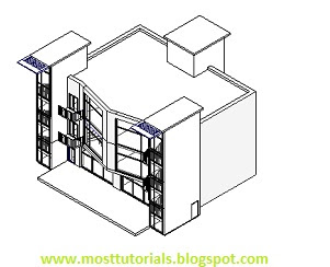
The 3D isometric view displays:
3 Click View menu ? Zoom to display the zoom menu.
The zoom menu lists the zoom options and their shortcut keys.
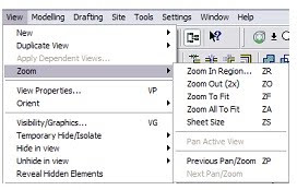

4 Click Zoom Out (2x).
In the drawing area, the view zooms out from the building model.

5 On the View toolbar, click the drop-down menu next to the Zoom command to display the
zoom options.
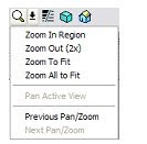


6 Click Zoom To Fit.

The view of the building model is sized to fit the available window.

7 Click in the drawing area, and type the shortcut ZR to zoom in on a region.
The cursor becomes a magnifying glass.

8 Click the upper left corner and lower right corner of the region to magnify; this is referred to
as a crossing selection.
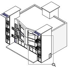
When you release the mouse button, the view zooms in on the selected area.
9 If you use a mouse that has a wheel as the middle button, you can roll the wheel to zoom the view. Use the wheel mouse to zoom out to see the entire building again.
If you do not have a wheel mouse, use a zoom menu command or the toolbar option to zoom
out.

NOTE As you zoom in and out, Revit Architecture uses the largest snap increment that represents less than 2mm in the drawing area. To modify or add snap increments, click Settings menu then Snaps

Zoom is also available using SteeringWheels. SteeringWheels provide 2D and 3D navigation
tools.

Using Steering Wheel in Revit Architecture
  • To display SteeringWheels, on the View toolbar, click .
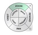
  • The Full Navigation wheel displays in the drawing area.
  • As you move the mouse, the wheel follows the cursor around the drawing area.
  • Move the cursor over the Zoom wedge of the wheel so that it highlights.
  • Click and hold the mouse button.
  • The cursor displays a pivot point for the Zoom tool.
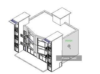


  • Drag the cursor down or left to zoom out.
  • Drag the cursor up or right to zoom in.
You can change the pivot point by releasing the mouse button, moving the wheel to the desired
location, and then using the Zoom tool again.
For more information about SteeringWheels, click the pull-down menu on the Full Navigation
wheel, and click Help. To define settings for SteeringWheels, click Settings menu ? Options,
and click the SteeringWheels tab.
  • To exit the wheel, press ESC.
Resize elements using drag controls in Revit Architecture
  • In the Project Browser, expand Views (all), expand Floor Plans, and double-click 2nd Flr. Cnst.
When drawing or modifying a building model, it is important to understand how to adjust the
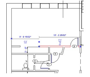
size of components in the drawing area. Small blue dots, called drag controls, display at the
ends of selected lines and walls in a plan view. Similar controls, referred to as shape handles,
display along the ends, bottoms, and tops of selected walls in elevation views and 3D views.
  • Type ZR, zoom in on the upper-left corner of the floor plan, and select the wall, as shown.
Notice the small blue dots that display at both ends of the wall. These are the drag controls.
  • Click and drag the left control, moving the cursor to the left horizontally, to lengthen the wall.
  • Click in the drawing area to deselect the wall.
Move an element
  • Scroll the view down so you can see the couch and table in the floor plan.
  • Select the Craftsman02 table, and on the Tools toolbar, click (Move).
Some commands, such as Move and Copy, require 2 clicks to complete the command. After
selecting the element to move, for example, click to specify the starting position, and click again
to specify the ending position. In this case, you want to move the table closer to the wall.
  • Click the lower-left endpoint of the table.
  • Click next to the lower wall, as shown.
    The table moves down, and the lower-left corner is placed at the move endpoint.
  • Select the plant, and drag it on top of the table.
Undo commands
  • On the Standard toolbar, click the drop-down menu next to (Undo).
All changes you make to a project are tracked. The Undo command allows you to reverse the
effects of one or more commands. In this example, you decide that you prefer the table in its
original position.
  • the Undo menu, select the second item in the list, Move.
Selecting the second item in the list will undo the last 2 actions. All commands are canceled up
to and including the selected command. The table and plant are returned to their original
locations.

NOTE
To quickly undo the previous action, on the Standard toolbar, click the Undo command, or
press CTRL+Z.

End a command

  • On the Basics tab of the Design Bar, click Lines.
Some commands, such as the Lines command, stay active or current until you choose another
command or end the current command.
  • Click in the drawing area to start the line, and click again to end it.
Notice that the Lines command is still active and you could continue to draw lines.
  • To end the command, use one of the following methods:
    • Choose another command.
    • On the Design Bar, click Modify.
    • Press ESC twice.
  • the file without saving your changes.

Read more...

Friday, April 30, 2010

Revit Architecture User Interface

Navigating the User Interface
One of the advantages of Revit Architecture is its ease of use, specifically its clear user interface. The Revit Architecture window is arranged to make navigation easy. Even the toolbar buttons are labeled, making it easy to understand what each button represents. Revit Architecture uses standard Microsoft Windows conventions. If you have used any other product that follows these conventions, learning Revit Architecture is much easier.In the following illustration, the user interface is labeled. In the steps that follow, you navigate and become familiar with the user interface.

Start a new project
On the Standard toolbar, click (New). This creates a new project based on the default template.


The Title Bar
Place the cursor at the top of the user interface.
The title bar contains the name of the project and the view that is currently open.


By default, new projects are numbered consecutively until saved with a new name. In addition,
the Level 1 floor plan view is the default open view.

TIP
The view opened and the view names are dependent on the template on which the project is based.

The Menu Bar
The menu bar across the top of the window includes standard menu names such as File, Edit,
and View. Click View menu ? Zoom.


Many of the commands have shortcut keys, which are listed on the menu. For example, the
shortcut key for Zoom in Region is ZR. While working in the drawing area, you type the required
key combination to perform the command. Another time-saving tool for selecting commands is to place the cursor in the drawing area and right-click. A shortcut menu displays a list of available commands, depending on the function you are performing and what is currently selected.


The Toolbar
Click Window menu ? Toolbar.
There are several toolbars across the top of the window beneath the menu bar. The toolbar
buttons represent common commands. You can control the visibility of the toolbars and turn
the text labels on or off using the Window ? Toolbar menu. You can use the toolbar grips to
resize and move each toolbar.


The Options Bar

  • Click Modelling menu ? Wall.
The bar beneath the toolbars contains wall design options. The Options Bar is context-sensitive
and varies depending on the tool or selected component.

  • Click Modelling menu ? Door.
The design options available on the Options Bar are now applicable to doors. On the left side
of the Options Bar, a door type is specified.

The Type Selector
The drop-down list on the left side of the Options Bar is called the Type Selector. Select the
drop-down list to view the list of doors.
The Type Selector is a context-sensitive drop-down list. When you select the Door tool, the Type
Selector displays a list of doors available in the project. The list of elements in the Type Selector
is identical to the elements listed in the Families branch of the Project Browser under the
respective category.

  • Click Modelling menu ? Wall.
  • In the Type Selector, select the drop-down list to see the walls that are available.
You can use the Type Selector in 2 ways:
  • You can select an element type before you add the element to the building model. For example, when you add a door, the door type that displays in the Type Selector is the door type that will be added to the building model.
  • You can use the Type Selector to change an element type after it has been added to the
    building model. In the drawing area, you can select any element and then change its type
    using the Type Selector.

The Design Bar
  • Click Window menu then Design Bars.
The Show Design Bars dialog displays.


The Design Bar is located on the left side of the interface, immediately below the Type Selector.
There are 10 tabs in the Design Bar, containing buttons grouped by function. You can control
which tabs display by selecting them in the Show Design Bars dialog.
Click OK.
Each tab contains frequently used commands that are also available from the menu bar.
Basics tab: commands for creating most basic building model components
  • View tab: commands for creating different views in the project
  • Modelling tab: commands to create model elements
  • Drafting tab: commands for adding annotation symbols and creating sheet details forconstruction documents
  • Rendering tab: commands for creating rendered images
  • Site tab: commands for adding site components and producing site plans
  • Massing tab: commands for creating conceptual designs with masses
  • Room and Area tab: commands for making room and area schemes and plans
  • Structural tab: commands for adding structural components to the project
  • Construction tab: commands for creating construction industry information
To access the commands in a tab, click the tab in the Design Bar. The respective commands
display on the Design Bar.

TIP: You can control the visibility of each tab by right-clicking on the Design Bar and selecting the tab from the shortcut menu.
The Project Browser
To the right of the Design Bar is the Project Browser. In the Project Browser, select Views (all).
You can use the Project Browser to quickly manage the views, schedules, sheets, reports, familie
and groups of your current project:
  • Right-click in the browser to add, delete, and rename views, families, and groups.
  • The browser is organized by view type (floor plans, elevations, 3D), family category (doorwalls, windows), and group name. Expand or collapse the browser list by clicking the + or next to the name.
  • To open a view, double-click its name.
  • You can also drag and drop from the browser into the drawing area, making it easy to add a family or group to the project or add a view to a sheet.
  • The browser is dockable, so you can reposition it by dragging the Project Browser title bar to a new location.
In the Type Selector, scroll through the sorting options available for the Project Browser.
  • Click Settings menu ? Browser Organization.
You can create and modify Project Browser organization schemes for views and sheets. After
creating a browser organization scheme, you can instantly change the sorting within the Project
Browser by selecting the scheme in the Type Selector.
  • In the Browser Organization dialog, click Cancel.

The Status Bar
  • On the Basics tab of the Design Bar, click Wall.
  • Place the cursor near the center of the drawing area. Do not click.
The cursor displays as a pencil.


In the bottom left corner of the window, the status bar provides information regarding what
you should do next. In this case, it tells you to "Click to enter wall start point."
  • On the Design Bar, click Modify to end the Wall command.
You can control the status bar visibility from the Window menu. The status bar also provides
information, in conjunction with tooltips, regarding selected elements in a view. When you
place the cursor over an element, it highlights and the status bar displays the element name.
  • Place the cursor over the elevation symbol arrow on the left side of the drawing area.
The elevation symbol consists of two parts: the main symbol and the elevation directional arrow
(a triangle). Make sure you place the cursor over the elevation directional arrow. It highlights
when the cursor is over it.
In the status bar, notice that the name of the highlighted element is Views : Elevation : West.
  • Press TAB, and notice that the highlighted element switches to the main elevation symbol, Elevations : Elevation : Elevation 3.
When attempting to select a specific element in a complex or crowded view, you can use the
status bar and TAB to switch between elements and select the desired element.

Read more...
Related Posts Plugin for WordPress, Blogger...

http://mosttutorials.blogspot.com/

civil engineering,electrical and other engg. software video tutorials.ebook and setups for free.... SAP2000,ETABS,SAFE,Autocad,revit Architecture,MS Project,Primavera ,Matlab,PSpice and much more

  © Blogger templates Newspaper III by Ourblogtemplates.com 2008

Back to TOP