Civil Engineering Blog with free video tutorials,and setups of sap2000,Etabs,safe,Autocad,Revit Architecture,primavera,MSproject,GIS,matlab,Papice,C++,and much more softwares
PrimaveraP6 is the most powerful, robust, and easy to use solution for globally prioritizing, planning, managing and executing projects, programs and portfolios. P6 is an integrated project portfolio management (PPM) solution comprising role-specific functionality to satisfy each team member's needs, responsibilities and skills. It provides a single solution for managing projects of any size, adapts to various levels of complexities within a project, and intelligently scales to meet the needs of various roles, functions, or skill levels in your organization.
Primavera P6 (was P5, now P6 v7.0) is a Project Management Software package that is used for managing and controlling project related activities. Resources representing labor, materials and equipment are used to track time and costs for the project. Slippage of projects' activities are updated resulting in the adjustment of time related Gant Bars
Primavera was once mostly used to handle very large and complex projects, especially in the engineering and construction business (e.g. to construct or maintain nuclear power plants). Today (2010),Oracle set a solution that addresses the need of Project Portfolio Management
P6 provides executives with a real-time view of their organization's project, program and portfolio performance. It equips managers with the right blend of usability, power and flexibility to effectively and efficiently execute on projects, and enables individuals across all levels of an organization to analyze, record, and communicate reliable information and make timely, informed decisions.
P6 makes it easy to: * Select the right strategic mix of projects * Assure project, IT and corporate governance * Enhance processes and methods * Improve project team collaboration * Measure progress toward objectives * Complete more projects successfully and with the intended payback.
Pipe2000 is a seamlessly integrated suite of software which includes the engines KYPipe, Steam, Gas, Surge, and GoFlow. For thirty years, KYPipe has developed and provided support for pipe system hydraulic flow analysis software. The strength and flexibility of the Pipe2000 suite of engines has made KYPipe an industry leader and made their software the most widely used pipe system hydraulic flow analysis software in the world. The Pipe2000 suite of software utilizes a consistent, intuitive Graphical User Interface; allowing the user to transition easily and efficiently between engines. This Pipe2008 package consists of 3 main items:
A New Model Initialization window opens in which you will be asked to whether to initialize your new model with definitions and preferences with existing .edb file... For instance click no in this problem
Define the ist Story
Choose "Grid Only" Model of ist story properly,run analysis and check for any improperly connected nodes.
Alternatively use ETABS' Uniform grid spacing
or Etabs custom grid spacing
Define Properties
Material Properties
Frame Sections
Slab/Wall Sections
Static Load Cases
Load Combinations
1-Material Properties
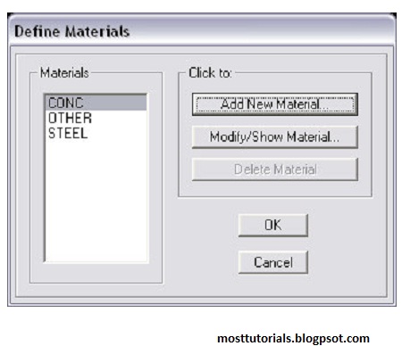
Add New Material Or Define Material Properties Suppose a Concrete of Fc'=4ksi
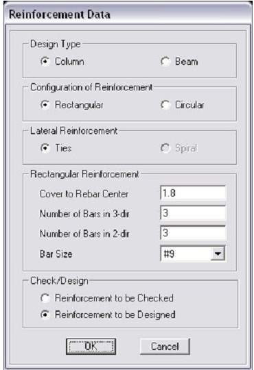
2-Frame Sections Add New Rectangular Section
Place The Concrete Coloumn on the Grid
ADD BEAM
ADD WALL SECTIONS
ADD SLAB
Define The Load Cases
Load Combinations
DDL = Design Dead + Live Load SDL = Service Dead + Live Load
Draw Coloumn,beams,shear walls......to be continued...
Read more...
The above figure shows a truss from several truss supposed to cover certain area.As shown the truss has a cantilever part ,its span equals 4 meters.The proposed truss depth is 3 m.The loads are shown as concentrated on tuss joints.The values of its load case are shown .
Use all the data you take in steel course to design and analyze steel truss.
Main Steps Of Modeling Truss in STAAD PRO
Entering Job information
Building model geometry
Defining member properties ,sections
Assigning Loads(Load Cases and combination)
Defining Pre-Analysis Print out,analysis type and Post-Analysis print out
Defining Design Requirements
Note :To see the image clearly click the image.
How to Start Staad Pro The Pic below shows how to start Staad Pro
Click the picture to enlarge
In New File select
Truss
Units (here KN and mm in this example)
The staad Graphical interface will appear as shown in below picture
1-Entering Job Information
2-Building Model (structure) Geometry
Defining Truss Geometry
One of the methods that you can construction lines and then draw on these lines the truss members
Noting that the no. of construction lines is excluding Ist line..
After clicking Snap Node/Beam ,use the mouse and connect between nodes created at the intersections of construction lines
How to see Diagram Labels(Nodes Numbers,Beam Numbers etc) Node and beam labels are a way of identifying the entities we have drawn on the screen, and very useful when dealing with the output results
3. Defining member properties, sections
Property
In which we can define or choose sections properties of the members of the truss.
Spec.:
In which we can define or choose members’ specifications.
Support:
In which we can define the supports properties (restraints).
Load:
In which we can define the applied loads, load cases, load combinations.
Material
In which we can define the material properties (ex. E, density, etc.)
Assume Preliminary Sections: Using The Canadian Steel Tables
All Top and Bot chords are one size L 55*55*3 All Diagonals and verticals are one size L 45 * 45* 3
Assigning the sections created to the model
Supports
By clicking on the support icon the shown window will appear. We have to create new kinds of supports
Use the mouse and click on the nodes according to its support type as shown below
4. Defining Loads The creation and assignment of load cases involves the following two steps:
1. First, we will be creating all 3-load cases.
2. Then, we will be assigning them to the respective members/nodes
For example
Dead Load Case can be Load Case No.1
Live Load Case can be Load Case No. 2 and Wind Load is the Case No.3
Also, we can define load combinations according to required.
For example, we can create a load combination
1.25 D.L. + 1.5 L.L + 0.8 W.L.
and In Dead Load Create the Self weight as
In each Load Case Creat the Nodal Loads on truss as specified before.Make sure of the direction of forces acording to global coordinates
After Creating the commond of (Perform Analysis-Check);We have to assign the members that want to be this type of analysis for it.
Click Assign and then use the cursor and choose all the members,thus all the members should be highlighted as shown below.
Pre-Print To add the Pre-Print Commond click" Define Commands"
For example here we have choosen to print the support reactions,member forces,joint displacements
Post Print Commands
Support reactions
Analysis results
Member Forces
Max Forces
Add which property you need and then use cursor to ASSIGN to which member in the truss
6-Defining Design Requirements Steps
1. To Specify steel design parameters,go to Design/Steel page from the left side of the screen.Make sure that under the Current Code selections on the top right hand side ,Canadian is selected.
There are many Design Commands in the STAAD Design subroutine.Here,we will use only to Check Code,regarding adequacy of members.
7-Analysis & Viewing Results STAAD Performs Analysis and Design simultaneously. In order to Perform Analysis and Design,select the Run Analysis option from the Analyze menu
When you select the Run Analysis option from the Analyze menu,the following dialog box appears.We are presented with the choice of 2 engines.the STAAD engine and the STARDYNEAdvanced Analysis engine.The STARDYNE Analysis engine is suitable for advanced problems such as Buckling Analysis,ModaL Extraction using various method ,etc
STAAD engine is suitable for this tutorial. Click on th Run Analysis button.
The soloving process is shown in pop up screen.
Visualization of Some Results
Note Generally,in any program ,try to make some checks about the shapes of defletions,BMD,SFD.Also check the level of reactions. Just to make sure that there is no significant nput error.
Viewing The OutPut File During the analysis process,STAAD creates an Output file .This file provides important information on whether the analysis was performed properly.
For example,if STAAD.Pro encounters an instability problem during the nalysis process,it will be reported in the output file.
Alternatively ,we can select the File/View/Output File/STAAD Output option from the top menu.
The Output File Its name is <>
As shown for example ,below are the results of the steel design check.
The End..
Read more...
This blog is created to provide various engineering and non engineering software video tutorials to students and professionals personal
http://mosttutorials.blogspot.com/
civil engineering,electrical and other engg. software video tutorials.ebook and setups for free.... SAP2000,ETABS,SAFE,Autocad,revit Architecture,MS Project,Primavera ,Matlab,PSpice and much more






 Posts
Posts


