Showing posts with label Autocad Tutorials. Show all posts

Thursday, March 24, 2011

Autocad 2004

Autocad 2004
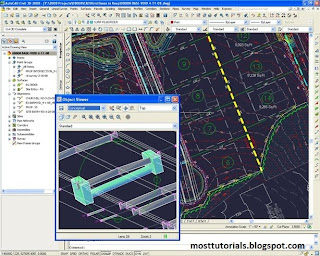
AutoCAD is a CAD(Computer Aided Design or Computer Aided Drafting) software application for 2D and 3D Designing and Drafting, developed and sold by Autodesk .inc Initially released in late 1982, AutoCAD was one of the first CAD programs to run on personal computers, and notably the IBM PC. Most CAD software at the time ran on graphics terminals connected to mainframe computers or mini-computers.
In earlier releases, AutoCAD used primitive entities — such as lines, polylines, circles, arcs, and text — as the foundation for more complex objects. Since the mid-1990s, AutoCAD has supported custom objects through its C++ API. Modern AutoCAD includes a full set of basic solid modeling and 3D tools. With the release of AutoCAD 2007 came improved 3D modeling functionality, which meant better navigation when working in 3D. Moreover, it became easier to edit 3D models. The mental ray engine was included in rendering, it was now possible to do quality renderings. AutoCAD 2010 introduced parametric functionality and mesh modeling.
AutoCAD supports a number of application programming interfaces (APIs) for customization and automation. These include AutoLISP, Visual LISP, VBA, .NET and ObjectARX. ObjectARX is a C++ class library, which was also the base for products extending AutoCAD functionality to specific fields, to create products such as AutoCAD Architecture, AutoCAD Electrical, AutoCAD Civil 3D, or third-party AutoCAD-based applications.

Read more...

AutoCAD 2010


AUTOCAD 2010
Autocad 2010 is one of the most exciting releases in AutoCAD. It offers new features across the board, so that almost everyone will find something valuable.
AutoCAD 2010 has several new features as

Dynamic Blocks

  • More compelling authoring environment
  • Easier to author dynamic blocks
  • flexible and powerful dynamic blocks with Constraint Parameters
  • Easy understanding and later edit authored behavior
  • A Test block without exiting Block Editor
Deployment
• Added the ability for a CAD Manager to create Advanced User Profiles
• Dynamic paths in the registry
• All user-customizable support files should be installed to Roaming AppData by default
• Allow choice for support content location


Read more...

AutoCAD Video Tutorials

AutoCAD 2010 Tutorial
Download Free AutoCAD 2010 Video Tutorials

http://rapidshare.com/files/362044134/01.Introduction.rar
http://rapidshare.com/files/362044136/02.AutoCAD_2009.rar
http://rapidshare.com/files/362280834/03.Basic_Drawing_Skills.rar
http://rapidshare.com/files/362280836/04.Working_with_Objects.rar
http://rapidshare.com/files/362293616/05.Organization___Inquiry.rar
http://rapidshare.com/files/362293617/06.Altering_Objects.rar
http://rapidshare.com/files/362303640/07.Working_with_Layouts.rar
http://rapidshare.com/files/362303641/08.Annotation.rar
http://rapidshare.com/files/362303642/10.Hatching.rar
http://rapidshare.com/files/362346975/11.Reusable_Content.rar
http://rapidshare.com/files/362346976/12.Additional_Drawing_Objects.rar
http://rapidshare.com/files/362353000/13.Plotting_Drawings.rar
http://rapidshare.com/files/362353004/14.Drawing_Templates_-_DWT.rar
http://rapidshare.com/files/362353005/15.Wrap_Up.rar

Read more...

Tuesday, March 15, 2011

WATERCAD Manual

Watercad manual

WaterCAD is a powerful yet easy to use program that helps engineers design and analyze complex
pressurized piping systems. WaterCAD’s powerful graphical interface (both in Stand-Alone and
AutoCAD mode) makes it easy to quickly lay out a complex network of pipes, tanks, pumps, and
more. You can use WaterCAD to:
• Perform steady-state analyses of water distribution systems with pumps, tanks, and control
valves.
• Perform extended period simulations to analyze the piping system's response to varying supply
and demand schedules.
• Perform water quality simulations to determine the water source and age, or track the growth
or decay of a chemical constituent throughout the network.
• Perform Fire Flow Analyses on your system to determine how your system will behave under
extreme conditions.
• Use the powerful Scenario Management features to mix and match a variety of "What If?"
alternatives on your system. Create multiple sets of hydraulic, physical property, operational,
initial setting, fire flow, cost, and water quality alternatives. Create and run any number of
scenarios by mixing and matching alternatives, then view and compare the results quickly and
easily with WaterCAD's flexible scenario management feature.


Contents

  • What is watercad
  • Installation
  • Learning WaterCAD
  • Contacting Heasted Methods
  • WaterCAD Main Menu
  • Quick Start Lessons
  • Starting a WaterCAD Project
  • Laying Out and Editing Tools
  • Hydraulic Elements Editor
  • Flex Tables
  • Scenarios and Alternatives
  • Modeling Capabilities
  • Cost Estimating
  • Presenting your Results
  • Engineering Libraries
  • GIS and Database Connections
  • Exchanging Data with CAD Software
  • Additional Features of the AutoCAD Version
  • Appendix A - Frequently Asked Questions
  • Appendix B - WaterCAD Theory
  • Appendix C - Scenario Management Guide
  • Appendix D - Haestad Methods Software
Download WaterCAD Manual
http://www.docstoc.com/docs/70246574/Water-CAD-User-Guide

Read more...

Thursday, April 29, 2010

Autocad Tutorial


The AutoCAD Screen

Application Button - This button displays commands for printing, saving, drawing utilities and other non-drawing tool.

Quick Access Toolbar - This is for quick access to common commands like New, Open, Save, Plot
Filename - The name of the current file you are working on.
Search Bar - Search for text in your drawing or search the help files.
Ribbon - The Ribbon has most of the commands/tools that you will use while you are working.

Tabs - A series of Tabs make up the Ribbon (Home, Insert, Manage, etc) and organize the Tools into common groups.

Panels - Contain a group of tools

Tools - These are the icon that start the commands you use to draw, modify, etc

Tool Tip - If you hover your mouse over a tool, a tool tip will appear to give your more information. Hold it longer for more info.

Drawing Space - These is where you draw your designs.

Command line - When you type a command, you will see it here. AutoCAD uses this space to 'prompt' you for information. It will give you a lot of information and tell you where you are in the command. Watch this line while learning.

Status bar - This allows to see and change different modes of drawing such as Ortho, Osnaps, Grid, Otrack, etc. You can right click this area to toggle between icons and text for this area.

Workspaces

With the introduction of AutoCAD 2009, a new screen layout was added. The program now allows you to work in different workspaces depending upon what you are working on. For example, the screen will look different if you are working on 2D than it will with 3D work. There is also an option for AutoCAD Classic (which is how the screen looked from Versions 2000-2008). This set of tutorials will deal with the new new workspace. Since you are a new user, you may as well learn the new interface. If you want to use the Classic interface, use the tutorials for AutoCAD 2008.

For the first 2 levels of tutorials, you will want to be in the 2D Drafting & Annotation workspace. Set this by clicking in the bottom right of the AutoCAD screen on the 'gear' icon as shown in the image below.
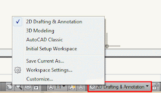
Changing Workspaces in AutoCAD 2010
Icons, Keystrokes and Menus

There are many ways to do things in most Windows programs. AutoCAD is no exception. Everyone will develop a way that works best for him or her. In this course, we will primarily be working with the keystroke commands. The reason for this is because they will work in most AutoCAD versions (including DOS versions), and in some other CAD programs. The icons work well, but as you will see, icons can be placed anywhere on the screen and can be difficult to find quickly. You may be working on another employee's computer that is set up differently than than what you're used to. The pull-down menus will access almost all commands, but are a slower way of doing things. Icons in AutoCAD 2010 are found on the ribbon, divided into panels - just click on the appropriate tab to open the panel you need..

Example: If you want to draw a line, you can do it a few ways:
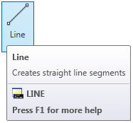


At the command line type: LINE (or) L and press the ENTER key.

Select the line icon from the DRAW Panel..Line Icon

All three approaches will do the same thing: prepare AutoCAD to draw a line where you tell it.


AutoCAD is a popular program because it can be customized to suit an individual's needs. The toolbars are a good example of this. You can have the toolbars you use most often on the screen all the time. You can easily make them go away so that you have more drawing space. You can also customize them so you have the most common commands on one toolbar. For example, the dimensioning toolbar is one that you will not want taking up space on your screen while drawing, but is very handy when you're dimensioning your drawing.

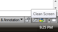
Clean Screen IconTo remove the ribbon and have the most drawing space available, click on the "Clean Screen" icon in the bottom right corner of the screen. To go back the to the standard display, click again on the same icon.
Read more...

Tutorial Autocad

Tutorial Autocad

Polar Measurements in AutoCAD

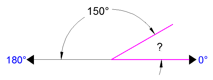
When drawing lines at an angle, you have to begin measuring the angle from 0 degrees, which is at the 3 o'clock position. If you drew a line at 90 degrees, it would go straight up. The example above (when you move your mouse over it) shows a line drawn at +300 degrees (270+30), or -60 degrees.

You might not always have an obvious reference point for 0 degrees. Look at the example below and place your mouse on the image to find out the angle in question.

?=30 DEGREES

In this example, you are given information about the lines, but not the angle AutoCAD needs to draw the line from the start point. What you are given though, is (a) the knowledge that 0° is at the 3 o'clock position (b) the knowledge that 180° is at the 9 o'clock position and (c) the angle between 180° and the line you want to draw is 150°. With this information, you can figure out what angle you need. Here is a fool-proof way of getting the angle you need:

1.) Start at the 0° position and measure counter-clockwise (+) to 180°.

2.) From 180°, measure clockwise 150° (-)

3.) Consider that you just went +180-150 and use that as an equation: +180-150=30

4.) Now you can draw your line using polar co-ordinates

Read more...
Related Posts Plugin for WordPress, Blogger...

http://mosttutorials.blogspot.com/

civil engineering,electrical and other engg. software video tutorials.ebook and setups for free.... SAP2000,ETABS,SAFE,Autocad,revit Architecture,MS Project,Primavera ,Matlab,PSpice and much more

  © Blogger templates Newspaper III by Ourblogtemplates.com 2008

Back to TOP