Tutorial Autocad
Tutorial Autocad
When drawing lines at an angle, you have to begin measuring the angle from 0 degrees, which is at the 3 o'clock position. If you drew a line at 90 degrees, it would go straight up. The example above (when you move your mouse over it) shows a line drawn at +300 degrees (270+30), or -60 degrees.
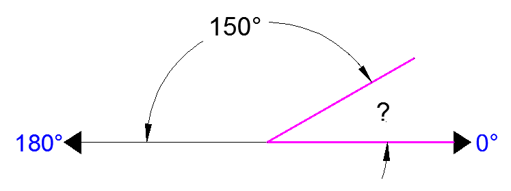
You might not always have an obvious reference point for 0 degrees. Look at the example below and place your mouse on the image to find out the angle in question.

In this example, you are given information about the lines, but not the angle AutoCAD needs to draw the line from the start point. What you are given though, is (a) the knowledge that 0° is at the 3 o'clock position (b) the knowledge that 180° is at the 9 o'clock position and (c) the angle between 180° and the line you want to draw is 150°. With this information, you can figure out what angle you need. Here is a fool-proof way of getting the angle you need:
1.) Start at the 0° position and measure counter-clockwise (+) to 180°.
2.) From 180°, measure clockwise 150° (-)
3.) Consider that you just went +180-150 and use that as an equation: +180-150=30
4.) Now you can draw your line using polar co-ordinates


0 comments:
Post a Comment